This website uses cookies so that we can provide you with the best user experience possible. Cookie information is stored in your browser and performs functions such as recognising you when you return to our website and helping our team to understand which sections of the website you find most interesting and useful.
News from Product Management: Design of a two-stage naXture actuator using the example of a puncher
After you have already experienced how the design of a single-stage naXture actuator works, we are now taking it to the next level:
High forces AND high speeds, combined in a compact, efficient actuator.
As an application example, we use a puncher here. It has to master two challenges in the smallest installation space:
- The fast approach and
- the powerful cutting of the material.
Requirements for the work task
A table punch for thin sheets is to be designed.
- Material to be punched: aluminium (A) & brass (M)
- Material thickness: Up to 1mm
- Average cycle time: 3 to 4 seconds
- Total stroke: 12 mm
The system layout provides for a uni-directional actuator, which is returned to its initial position via a spring return – after punching.
Interpretation of the work task
To determine the punching force FP in [N], the following approximation is used:
FP = U * t * Rm * 0.9 * f
U: Circumference of the cutting punch in [mm]
t: Sheet thickness in [mm]
Rm: Tensile strength in [N/mm²]
f: Factor when using shear bevels between 0.5 – 1.0
The following numerical values are used:
- U = 10 mm
- f = 1.0
- tA = 0.8 mm; tM = 0.3 mm
- RM_A = 180 MPa; RM_M = 400 MPa
This results in the following force requirements for the punching process:
FP_A = 5090 N
FP_M = 3393 N
Selecting the naXture actuator
If we now take the force FP_A and apply 60% to it, we get our maximum application force Fmax:
Fmax= FP_A * 1.6 = 5090 N * 1.6 = 8144 N
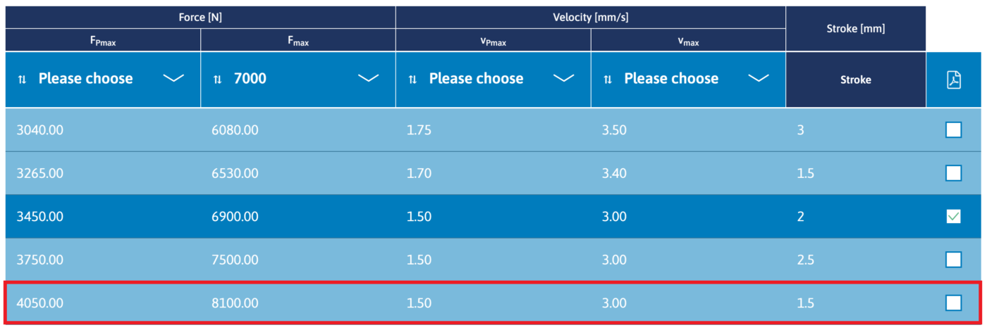
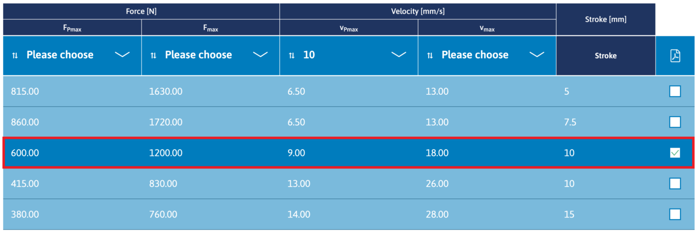
With this Fmax we can now select the appropriate configuration in our selection tool.
The “best match” here is the actuator with Fmax = 8100 N. With a force of FPmax = 4050 N. This value is about 25% below the punching force FP_A. This means that there is sufficient reserve for the dynamics in the punching process.
If you do not yet know how to use our sample tool, we recommend the following article:
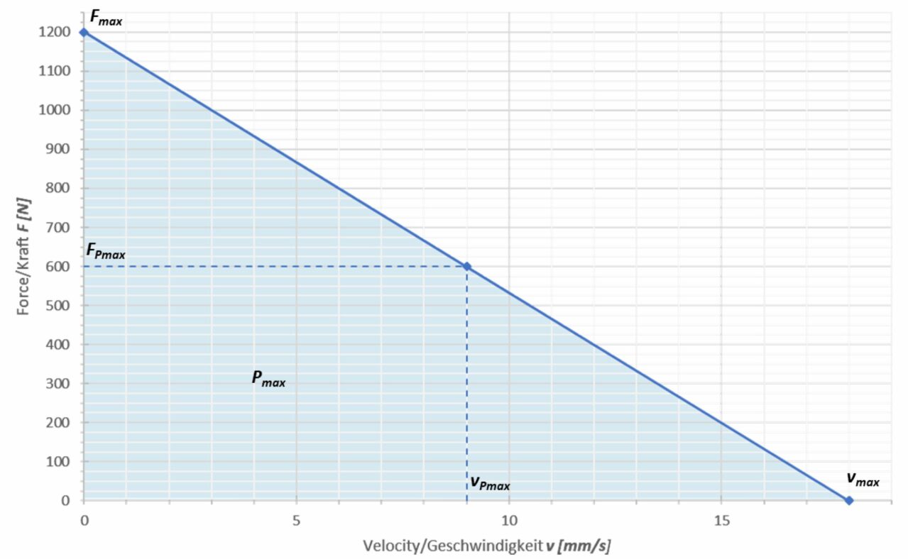
Force/speed diagram of the selected actuator:
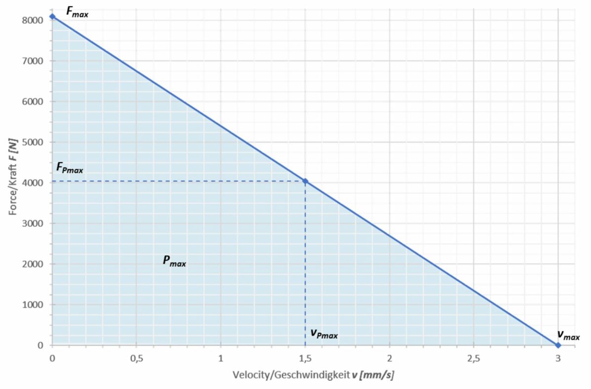
With a maximum speed of vmax = 3 mm/s, we cannot meet the requirement for a cycle time of 3 s, over a stroke of 12 mm, in a single-stage actuator configuration.
As is already known from classical hydraulics, two-stage systems can provide a solution here: a first stage, with a reduced hydraulic cross-section, allows faster movement, while a second stage, with a larger hydraulic cross-section, is used to generate high forces. This is exactly the approach we can also implement with naXture.
- Rapid approach run over 9 mm with a reduced cross-section and…
- …a powerful stroke of 3 mm with increased force over an enlarged cross-section.
We divide the total stroke of the punching actuator of 12 mm into 2 areas:
The selected actuator, for the range with increased force, has a speed of vPmax = 1.5 mm/s in the range of maximum power. This results in a time requirement of 2 s for the distance of 3 mm; for the approach travel, one second then remains for the distance of 9 mm. This allows us to pick an actuator configuration with a speed vPmax of 9 mm/s.
The Sample Tool provides us with a suitable actuator:
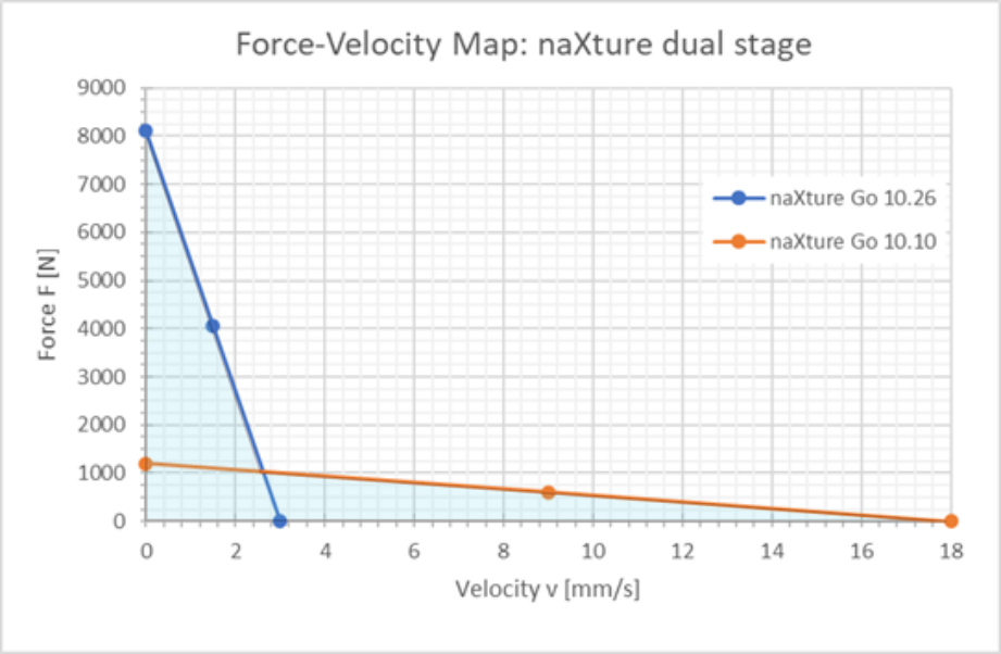
If we now put these two configurations on top of each other in a force-velocity diagram, we obtain the characteristic diagram of a two-stage actuator, similar to the human muscle:
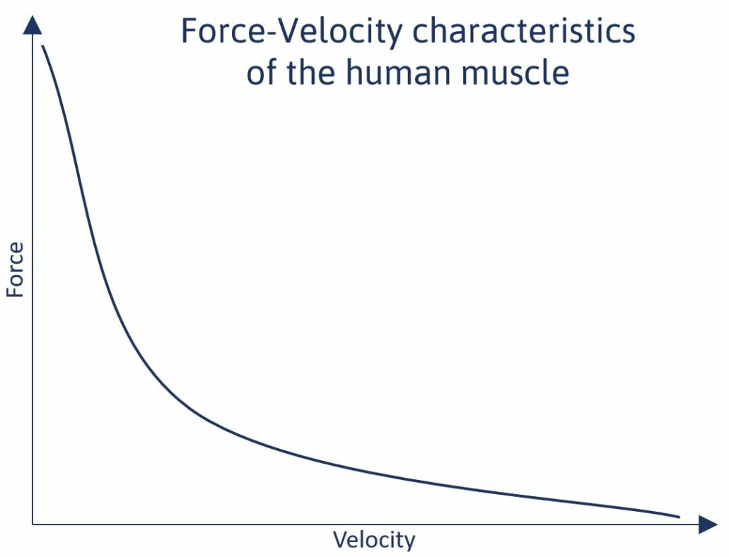
Here, for comparison, the qualitative characteristic curve of the human muscle.
Verification of the interpretation
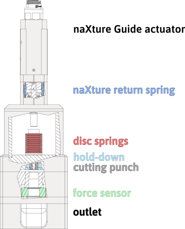
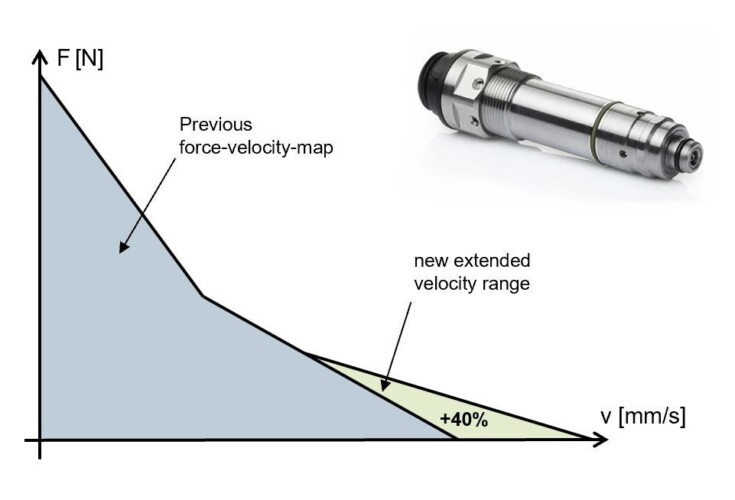
Structure of the punching application:
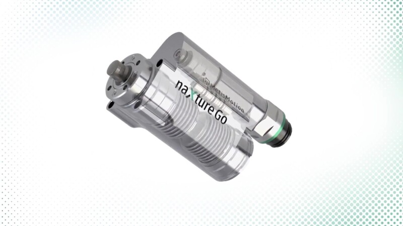
- naXture Guide actuator
- The naXture actuator designed for this application with inherent pressure feedback measurement
- naXture return spring
- The spring integrated for resetting the unidirectional naXture Guide actuator
- disc springs
- Disc spring package for returning the cutting punch
- force sensor
- Integrated force sensor for measuring the force characteristic during the punching process
- outlet
- Opening to eject the punching result
The naXture Guide actuator shown above was designed with two stages in the previous step. In this step we will now detail the system:
- Superimposition of the force-displacement characteristic of the spring return.
- Evaluation of the influence of a disc spring pack for the hold-down.
- Influence of friction from the piston seal.
Sequence of the punching process:
- Distance s1 [ 0; 9 ] mm:
the output piston of the actuator makes an approach run. At the end of the distance s1 the output piston meets the cutting punch - Distance s2 [ 9; 10.5 ] mm:
the cutting punch moves up to contact with the workpiece; the cutting force is applied - Distance s3 [ 10.5; 11.5 ] mm:
the cutting punch punches - Distance s4 [ 11,5; 12 ] mm:
pushing out the punched material
The design of the actuator provides for the use of a spring return. The selection of the spring rate and preload has been chosen in such a way that the output piston – after switching off the electrical supply – moves back to the initial position:
- Spring rate cF: 4.69 N/mm
- Preload force FVF: 141 N
- The spring is tensioned over the entire stroke.
In order for the cutting punch to retract after the punches, a pack of disc springs is used:
- Clamping path s: 0.41 mm
- Clamping force Fs (0,41mm): 690 N
- Number of disc springs: 10
- Preload FVT: 124 N
- Stroke: 3 mm
The tensioning of the spring pack begins when the output piston hits the cutting punch.
The friction of the piston seal can be measured while mounting the output drive into the actuator housing.
A typical value for the seal used is about 70N. The breakaway force of the output piston is assumed to be 100 N.
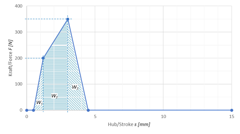
The following diagram shows the curve of the internal forces over the stroke:
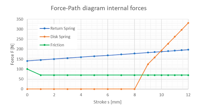
In the following table you will find the determined values (aluminium) for:
- The distance travelled,
- the internal forces from friction, return spring and disc spring assembly,
- the punching force,
- the associated velocities from the force-velocity diagrams of the actuator stages
- and the corresponding times.
| stroke [mm] | system force [N] | friction [N] | return spring [N] | disc spring [N] | punching force [N] | velocity [mm/s] | time incr. [s] | time abs. [s] |
|---|---|---|---|---|---|---|---|---|
| 0,0 | 241.0 | 100.0 | 141.0 | 0.0 | – | 14.4 | 0.00 | 0.00 |
| 1,0 | 215.7 | 70.0 | 145.7 | 0.0 | – | 14.8 | 0.07 | 0.07 |
| 2,0 | 220.4 | 70.0 | 150.4 | 0.0 | – | 14.7 | 0.07 | 0.14 |
| 3,0 | 225.1 | 70.0 | 155.1 | 0.0 | – | 14.6 | 0.07 | 0.20 |
| 4,0 | 229.7 | 70.0 | 159.7 | 0.0 | – | 14.6 | 0.07 | 0.27 |
| 5,0 | 234.4 | 70.0 | 164.4 | 0.0 | – | 14.5 | 0.07 | 0.34 |
| 6,0 | 239.1 | 70.0 | 169.1 | 0.0 | – | 14.4 | 0.07 | 0.41 |
| 7,0 | 243.8 | 70.0 | 173.8 | 0.0 | – | 14.3 | 0.07 | 0.48 |
| 8,0 | 248.5 | 70.0 | 178.5 | 0.0 | – | 14.3 | 0.07 | 0.55 |
| 9,0 | 377.4 | 70.0 | 183.2 | 124.2 | – | 12.3 | 0.08 | 0.63 |
| 9,5 | 414.2 | 70.0 | 185.5 | 158.7 | – | 2.8 | 0.18 | 0.81 |
| 10,0 | 451.1 | 70.0 | 187.9 | 193.2 | – | 2.8 | 0.35 | 1.16 |
| 10,5 | 5577.9 | 70.0 | 190.2 | 227.7 | 5090 | 0.9 | 1.07 | 2.23 |
| 11,0 | 4087.7 | 70.0 | 192.5 | 262.2 | 3563 | 1.5 | 0.67 | 2.90 |
| 11,5 | 1070.6 | 70.0 | 194.9 | 296.7 | 509 | 2.6 | 0.19 | 3.10 |
| 12,0 | 598.4 | 70.0 | 197.2 | 331.2 | – | 2.8 | 0.18 | 3.28 |
The following graphs show the force curve for aluminium over the stroke as well as the corresponding force/velocity diagram:
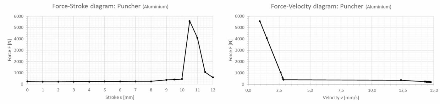
With regard to the values for the punching force and the duration of the punching cycle of 3.3 s, the design is within the range of requirements.
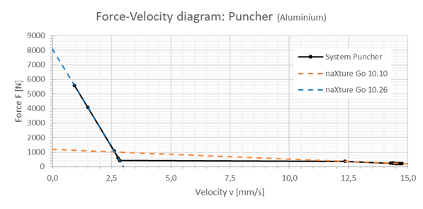
If we compare the graphs for the individual actuators with those of the selected system, we see that the calculated values for the forces and speeds lie on or within the limits of the actuator characteristics:
To complete the picture, here are the diagrams of the force curve for brass over the path and the corresponding force-velocity diagram:
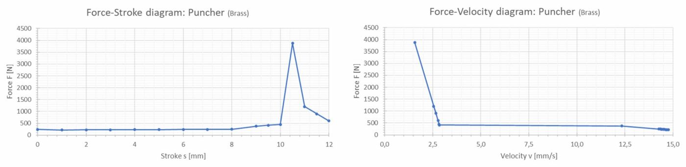
The actuator design is also suitable for punching brass. The lower force level resulting from the thinner sheet metal results in a shorter cycle time of less than 2 seconds.
Thus, the required average cycle time is then within the requirements of 3 seconds.
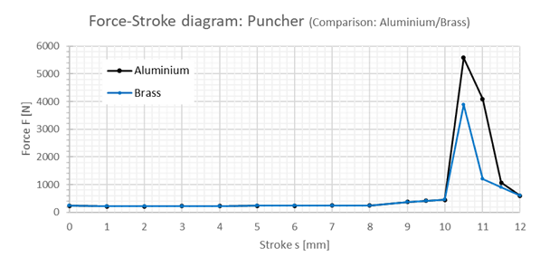
Here again is a comparison of the two force-displacement diagrams:
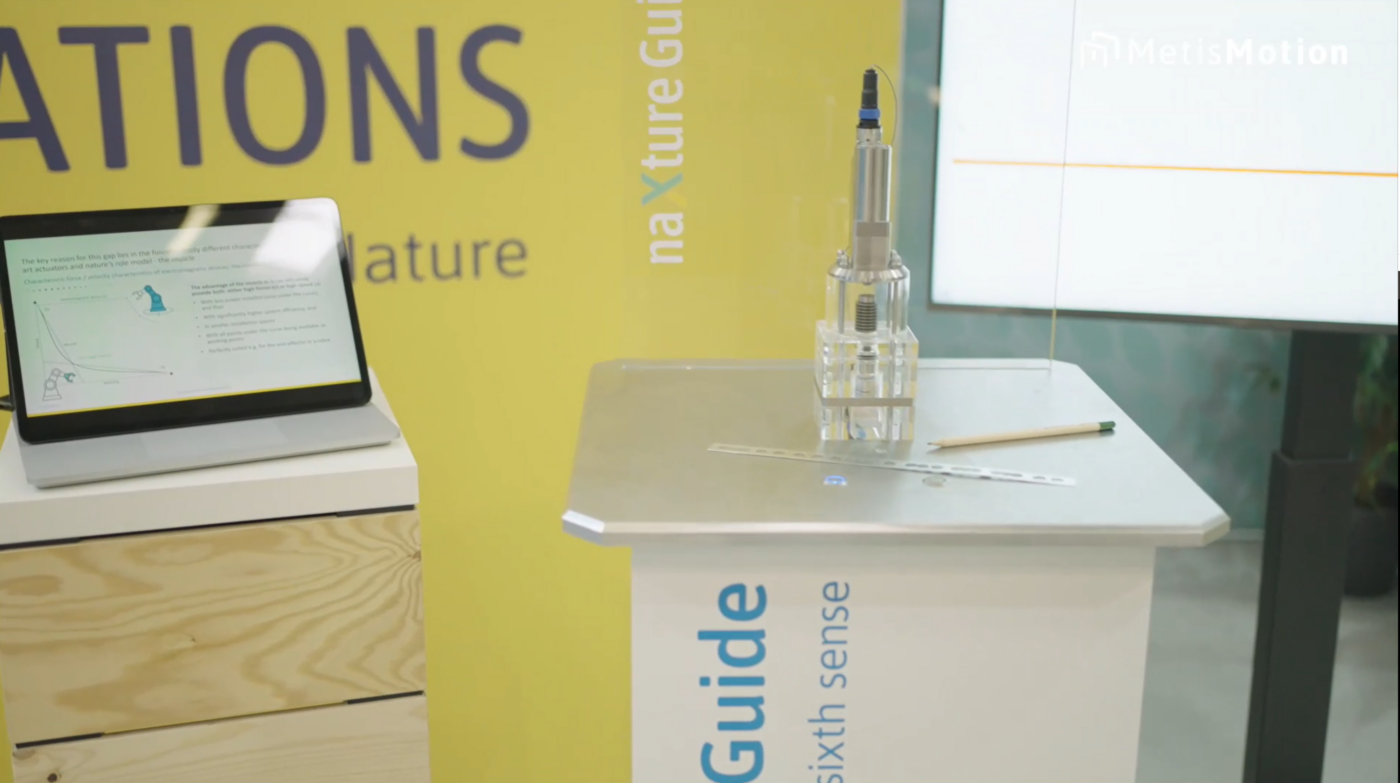
The designed punching application presented at automatica 2022
You want to understand how naXture Guide enables the shown monitoring of the punching process?
Our next blog entry will provide the answer!
Got your interest ?
Then why not also take a look here
- MetisMotion presents “Ultimate design flexibility for YOU!” with naXture @ automatica 2023

- MetisMotion – Join our SUCCESS STORY

- News from Product Management: Design of a two-stage naXture actuator using the example of a puncher

- MetisMotion introduces naXture Guide – the world’s first actuator with the sixth sense @ automatica 2022

- MetisMotion @ automatica 2022 || naXture Guide Launch

- News from Product Management: naXture in the fast lane
- Outlook R&D – Grant project PIA

- News from the product management: Selecting a naXture actuator for your actuation task – Unlatching
- MetisMotion presents naXture