This website uses cookies so that we can provide you with the best user experience possible. Cookie information is stored in your browser and performs functions such as recognising you when you return to our website and helping our team to understand which sections of the website you find most interesting and useful.
News from the product management: Selecting a naXture actuator for your actuation task – Unlatching
We are continuing our blog series to support our customers in selecting our actuators and added a new application: “Unlatching”.
Application task “unlatching” explained – step by step – from the analysis to the verification of the selection in the force-velocity map.
Requirements for the work task
Actuation task:
A latch is to be opened.
- With a force of 350N, a self-locking mechanism is disengaged and the mechanism is unlocked. The actuator then pushes the latch into an end position.
- The total stroke of 15mm is divided into three parts:
1. attaching the actuator to the mechanism (0.5mm),
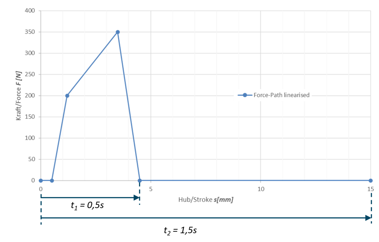
2. unlatching (4mm) and 3. pushing into the end position (10.5mm). - The total procedure should be completed in 1.5 seconds, with 0.5 seconds available for unlatching.
Requirements:
- A force reserve is to be provided: 50% of the nominal force.
- Safety state is “Normally Retracted“: in powerless state, the actuator automatically returns to the start position.
Analyses of the actuation task
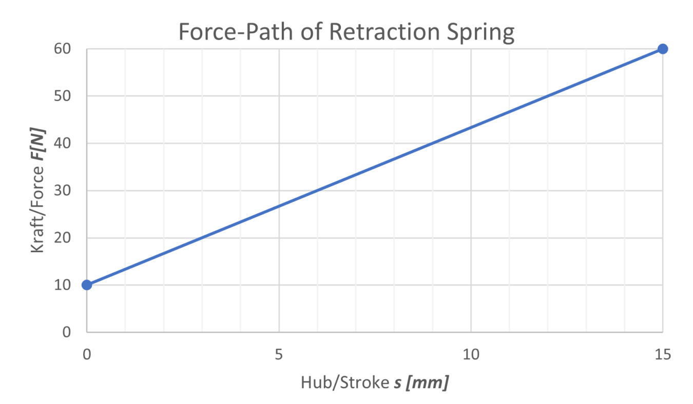
1. Creating a force-path diagram
2. Setting up the requirement for the positioning time
3. Determining the load data:
- Load: FApp = 350N
- Stroke: 15mm
| Operating point | Stroke s [mm] | Force F [N] | Stroke Δs [mm] | Time t [s] |
|---|---|---|---|---|
| 1 | 0 | 0 | – | – |
| 2 | 0,5 | 0 | 0,5 | – |
| 3 | 1,2 | 200 | 0,7 | – |
| 4 | 3 | 350 | 1,8 | – |
| 5 | 4,5 | 0 | 1,5 | 0,5 |
| 6 | 15 | 0 | 10,5 | 1,5 |
Calculation of the load data
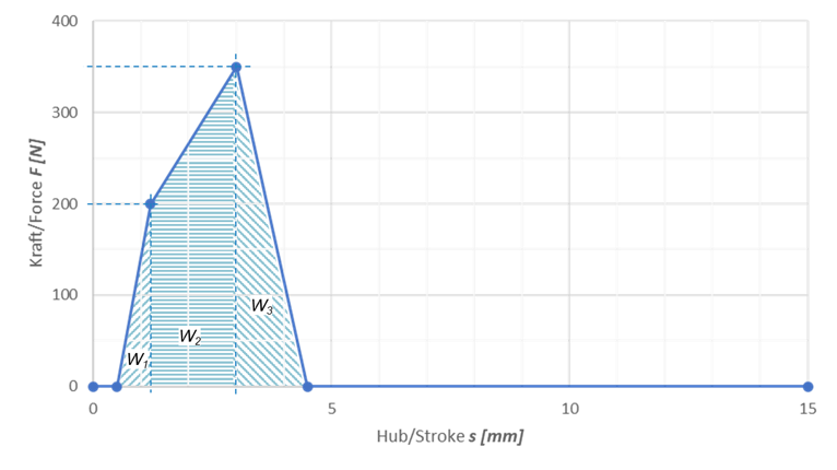
4. Calculation of the mechanical work W[J]:
- W = F * s
| Work W [J] | |
|---|---|
| W1 | 0,07 |
| W2 | 0,63 |
| W3 | 0,18 |
| Summe | 0,88 |
During the unlatching process…
- a mechanical work Wtotal of 0,88J is applied.
- A mechanical power of aprox. 1,76W (0,88J/0,5s) is required.
Selecting the actuator
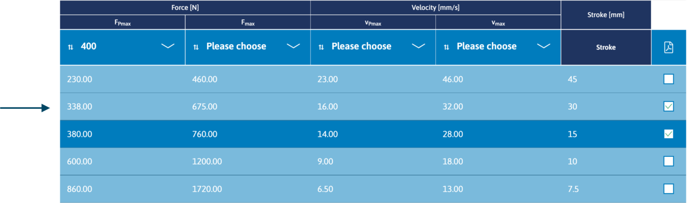
5. Determining the force FPmax to select the actuator
- During unlatching, a work of 0.88 J is applied over a stroke of 4mm.
For the first estimation of FPmax we can assume 0,88J/0,004m = 220N and a surcharge of 65% resulting in 363N. - Additionally, we can take into account the requirement for a force reserve of 50% of the nominal force: Fmax = 350N * 1,5 = 525N
The displayed „Best Match“ then results in:
| FPmax | Fmax | vPmax | vmax | Hub |
|---|---|---|---|---|
| 338,00 | 675,00 | 16,00 | 32,00 | 30 |
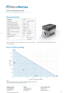
Downloading the technical information sheet
6. Download the technical information sheet of the actuator:
| FPmax | Fmax | vPmax | vmax | Hub |
|---|---|---|---|---|
| 338,00 | 675,00 | 16,00 | 32,00 | 30 |
Verification of the force-velocity map
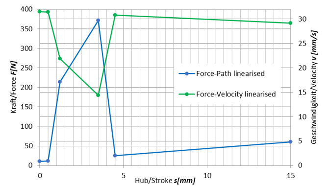
7. Checking the requirements for the actuating speed:
- A preloaded spring should be used to retract the actuator in the powerless state:
FRe(s) = 10N + 3,334 N/mm*s - In order to determine the extension speed of the actuator at the respective operating points and thus the positioning times to be checked, the path-dependent restoring force FRe(s) must be superimposed.
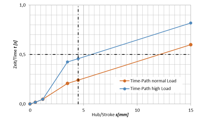
- From the force-velocity diagram of the technical information sheet, the positioning speeds can then be obtained and the positioning times calculated:
| Operating point | Stroke s [mm] | Force F [N] | Velocity v [mm/s] | Stroke Δs [mm] | Time Δt [s] | Time abs. t [s] |
|---|---|---|---|---|---|---|
| 1 | 0 | 10 | 31,53 | – | – | 0 |
| 2 | 0,5 | 11,67 | 31,45 | 0,5 | 0,02 | 0,02 |
| 3 | 1,2 | 214 | 21,85 | 0,7 | 0,03 | 0,05 |
| 4 | 3 | 371,7 | 14,38 | 1,8 | 0,16 | 0,21 |
| 5 | 4,5 | 25 | 30,81 | 1,5 | 0,03 | 0,24 |
| 6 | 15 | 60 | 29,16 | 10,5 | 0,36 | 0,6 |
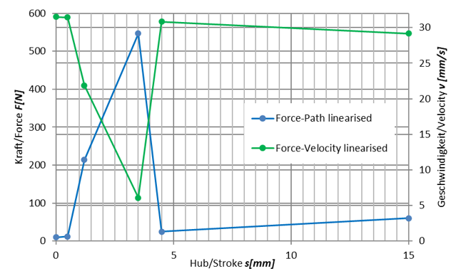
8. In addition, the actuating speed at an additional load of 50% of the nominal force is to be checked – the procedure is in accordance with the previously prepared calculations:
| Operating point | Stroke s [mm] | Force F [N] | Velocity v [mm/s] | Stroke Δs [mm] | Time Δt [s] | Time abs. t [s] |
|---|---|---|---|---|---|---|
| 1 | 0 | 10 | 31,53 | – | – | 0 |
| 2 | 0,5 | 11,67 | 31,45 | 0,5 | 0,02 | 0,02 |
| 3 | 1,2 | 214 | 21,85 | 0,7 | 0,03 | 0,05 |
| 4 | 3 | 546,67 | 6,08 | 1,8 | 0,38 | 0,43 |
| 5 | 4,5 | 25 | 30,81 | 1,5 | 0,03 | 0,46 |
| 6 | 15 | 60 | 29,16 | 10,5 | 0,36 | 0,82 |
9. Verification of the requirements:
- The actuator can provide the required forces:
Both for the nominal force and with the required reserve of +50%. - The required actuating times for unlocking and extending to the end position can be confirmed.
Even in the case of additional load, the operating velocity remains within the requirement.